You will now get the selected texture directly as an overlay.
You will now get the selected texture directly as an overlay.
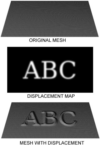
image source: Wikipedia
You will probably want to fix this up in Photoshop (Photopea).
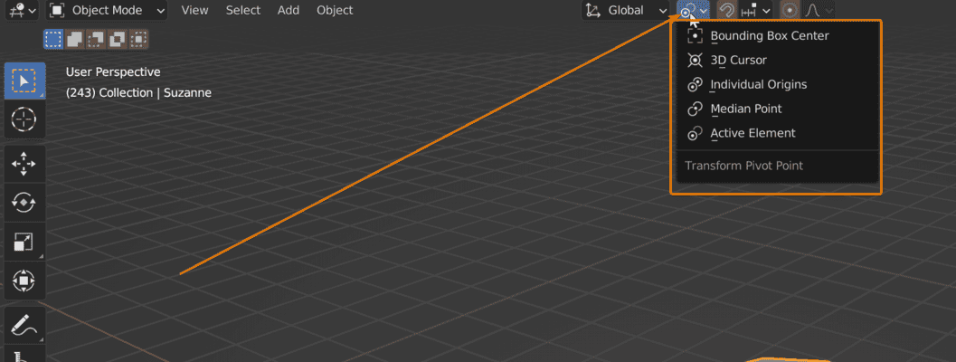
Set it to "3D Cursor"
Things are looking like this now? Great, then click "Bake"!
A normal map with no artifacts or distortions: this is the kind of result we want.
Press P and then click on Selection